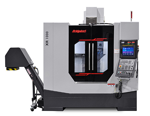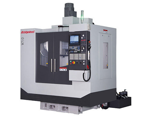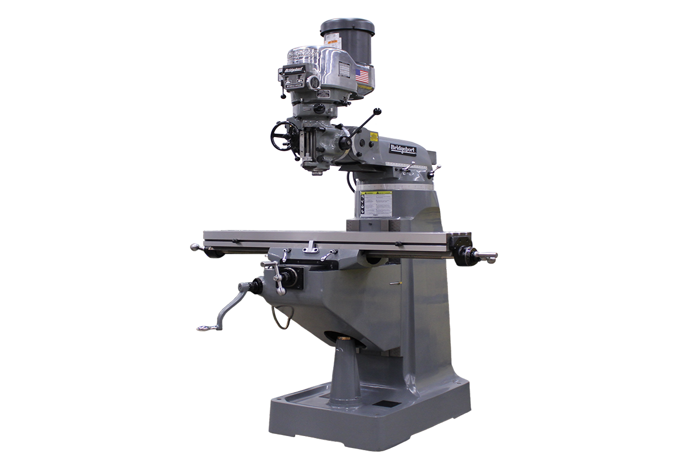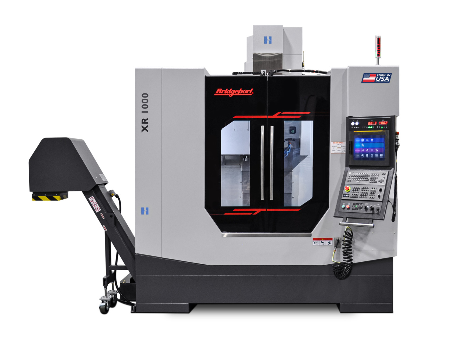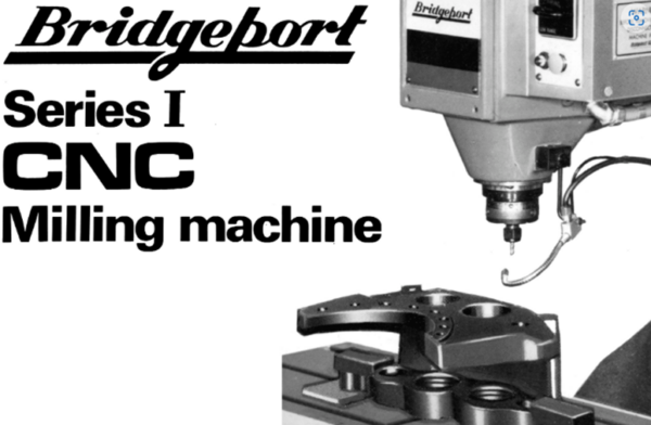
Bridgeport Series 1 CNC Milling Machine
The Bridgeport Series 1 CNC milling machine is a specially designed vertical milling machine forming part of a totally integrated package of milling machine and control dedicated to the requirements of NC Operation.
The control system includes a micro-computer, the Bridgeport Operating System Software (BOSS) and serial line interface for data input. The micro-computer, with editor, stores programme segment.
The X, Y and Z axes drives are new and unique. The table, saddle and knee are of extremely rigid structure, providing great overall stiffness. The ballscrew drives for the X and Y axes are suspended clear of the operator’s working area and in such a manner as to eliminate table deflection.
The control logic has a system resolution of 0.001mm (0.0001”) and is capable of multi-axis contouring through 3 axis linear and 2 axis circular interpolation.
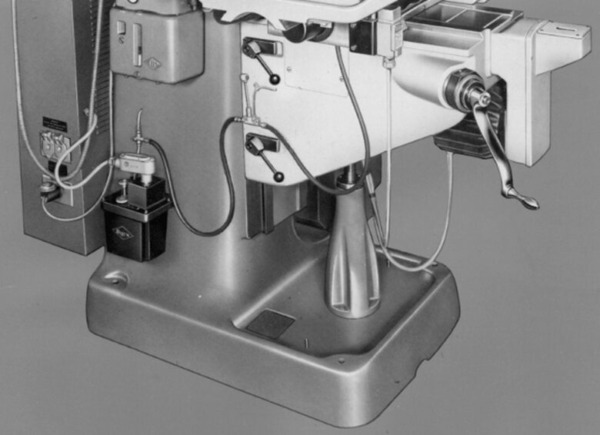
The CNC Base and Knee
To ensure the consistent accuracy demanded by Numerically Controlled operation, the base and column of the Bridgeport CNC is a one-piece, heavily ribbed grey iron casting. This provides rigidity and stiffness for years of accurate and economical production.
The knee and saddle are specially designed to provide maximum support for the extra large table and rigid construction ensures maximum accuracy under all cutting conditions.
Unique Knee Design
The knee, employing a unique design, provides an extra wide bearing surface to the saddle and the column dovetail resulting in high accuracy and stability for the table movement.
The mounting of the Y axis drive motor allows maximum operator accessibility from all positions, whilst also completely shielding the motor from chips, dirt, and coolant.
Knee Position Clamping
A special dual clamp arrangement operating at the top and bottom of the knee ways provides distortion free knee (column) clamping over the full 365mm (14”) travel.
X and Y Axis Drives
The drives to the X and Y axis through 25mm (1”) diameter totally enclosed, hardened, and ground ballscrews supported by steep angular contact thrust bearings are mounted in rigidly constructed brackets.
Factory set mechanical counters are driven off the ballscrew in the X and Y axes to provide a clearly displayed readout of the table and saddle positions.
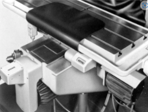
Chrome-plated Slideways
The more important slideways (knee to cross-slide and cross-slide to table) of the Bridgeport CNC have been hard chrome plated by Poeton-Tibon precision process to maintain the original accuracy over a longer period of time.
This process enables the slideways to be hard chrome plated to a uniform thickness of approximately 0.05mm (0.02”). The hard-chrome deposit is slightly porous and therefore provides and ideal lubricant absorbing surface with an extremely low co-efficient of friction.
Automatic Lubrication
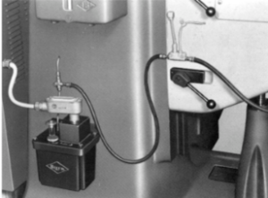
The Bridgeport Series 1 CNC is fitted with an automatic lubrication system that lubricated slideways and ballscrews for the X, Y, and Z axes and in addition the same system lubricates the bevel gears of the knee elevating mechanism.
Correct lubrication thus ensures a longer accurate life, reduces maintenance and makes the machine more sensitive and easier for the operator to work.
The low level protection will place the machine a SETUP condition if insufficient oil is detected at any programmed stop.
Recirculating Ballscrews
The requirements of modern engineering demand highly efficient methods of transferring motion and power. The preloaded recirculating ballscrew system employed by the Bridgeport Series 1 CNC adequately fulfills these requirements.
Conventional threads suffer the disadvantage of low mechanical efficiency due to power losses caused by friction between the nut and leadscrew. The ballscrew system used reduces these disadvantages by offering almost frictionless operation of ball bearings between nut and shaft, resulting in an extremely high efficiency level.
The CNC Table Features
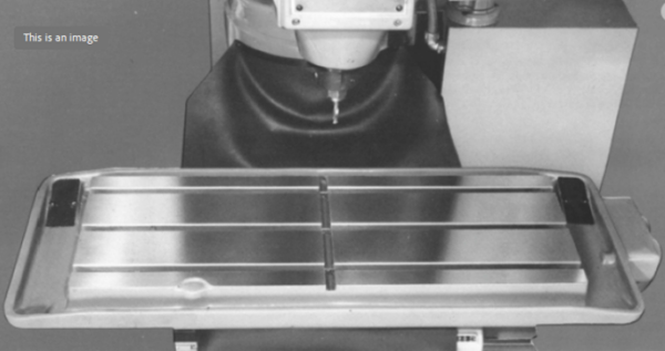
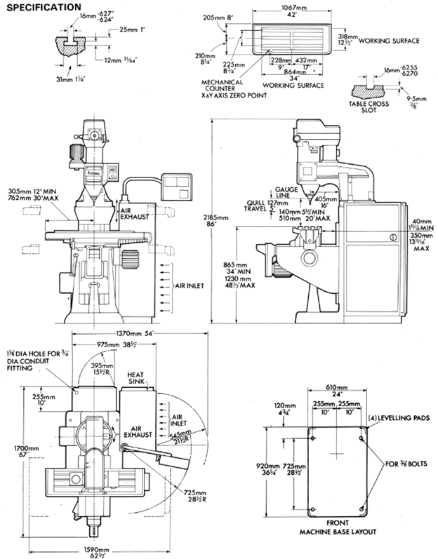
The large working surface of the table 864mm x 318mm (34” x 12”) ensures that the component is fully supported over the complete X, Y travel of 455 x 305mm (18” x 12”).
The overall table design embodies deep gutters for the efficient and rapid removal of coolant.
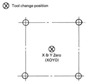
The table incorporates a boss located at the absolute zero position of the X and Y axes i.e. where the mechanical axis counters display two zero readings.
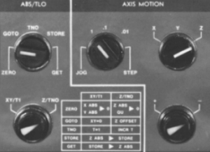
The control incorporates a variable step axis jog feature and a fully floating programmable zero position in all axes, thus facilitating ease and speed of component set-up and rapid job interchangeability. This position (the X, Y zero co-ordinates) can be set at any point within the travel limits and a panel pushbutton permits a return to the X, Y zero point at anytime.
Extended Deep Saddle
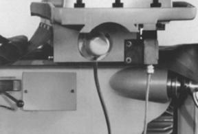
The saddle is deeper, longer and heavier than conventional knee-type machines for better support and maximum stiffness. This design also permits the axis drive motor to be mounted in such a way as to reduce table deflection to a minimum.
The CNC Milling Head
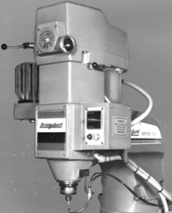
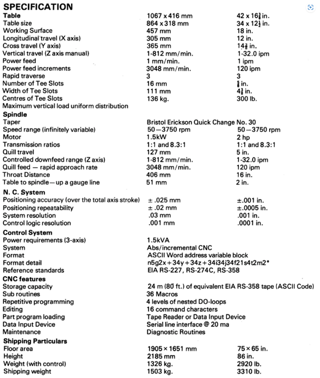
The head, mounted on a rigid ram for increased stability, has a 1.5Kw (2Hp) continuous duty, fan cooled AC induction spindle drive motor which provides infinitely variable spindle speeds from 50 – 3750 RPM.
The spindle speeds are divided into two ranges with no gap between them; a lower range of 50 – 500 is obtained by using the back gear arrangement and the higher range of 500 – 3750 RPM is obtained through direct drive.
The successful unique patented reverse flow air cooling system employed on the Bridgeport BR2J2 is adopted for the CNC milling head. This not only reduces possible distortion from heat build up in the spindle and cools quill areas but by maintaining the operating temperature within 20°F of ambient at all time, increasing belt and bearing life.
Facility for a large component set-up is provided by the deep throat distance of 406mm (16”) and a maximum height from the table to the spindle quill of 510mm (20”).
The drive of the axis is achieved by a timing belt from the axis stepping motor rotating the nuts around a preloaded and recirculating ballscrew mounted concentric with the quill.
Z Axis Drive
This design ensure maximum utilization of the power generated whilst providing precise depth control as the cutting forces are counteracted directly through the axis of rotation of the spindle.
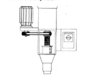
Tool Length Offset
The Z axis incorporates the facility for calling up to 24 random tool lengths in any one programme. These are accommodated in a tool length offset (TLO) register enter either manually or from tape.
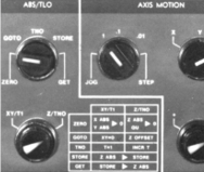
Bridgeport CNC Control
The Bridgeport CNC Systems is a micro-computer based machine tool control designed to provide the functions of hard wired random logic controls plus the capability of utilizing computer software techniques. The control programme text is stored and may be input to that storage from an optional tape reader or from an external CRT of teleprinter – 20 ma serial remote interface for such remote equipment is supplied. The storage capacity is equivalent to 24m (80ft) of prepunched tape and can contain programme text in the form of Word Address data to RS-274C. This text can include up to 36 Macro subroutines, each having variables that can be modified in the call statement. The text has additional repetitive sub programme capability with looping techniques using up to 4 levels of nested looping instructions. The text editor residing in the micro-computer memory enables the entering, altering or outputting of the text through the use of 16 command characters. The control permits 3 axis linear and 2 axis circulation (XY, YZ, XZ planes) interpolation with vector velocity control. Absolute or incremental data is permitted. There are 8 canned Z cycles. 24 Z axis tool length offsets and three canned milling cycles (facing, boring and pocketing). A feed interlock is provided if the spindle is not operating.
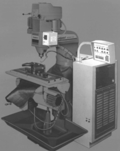
CONTROL FEATURES
Bridgeport Operating System Software (BOSS)
BOSS is a comprehensive software system designed for the NC user. It consists of a system monitor, control function service routines including linear and circular interpolation, and a powerful user oriented text editor, BOSS is an embedded non volatile read only memory, it takes control of the system as soon as power is applied.
Word address variable block input format
American Society Code for Information Interchange (ASCII) language code input format for contouring/positioning machines is used conforming to EIA RS 274C. 29G and 5M codes have been assigned. Leading and trailing zeros may be dropped and a shortened format can be used for radius arcs that extend past one quadrant.
Absolute/Incremental
G90 selects absolute data input. G91 selects incremental data input. G92 can be used to preset the XYZ absolute registers to any desired value.
Resolution/maximum move
Programing resolution is 0.001mm (0.0001”). X, Y, and Z-axis drive motor resolution is 0.025mm (0.001”). Maximum input is 9999.99 mm (999.9999”)
Direct Feedrate Coding
Feedrates are programmed with a range of 1 to 812mm/min in 1mm/min increments (0.01 to 32.0 IPM increments).
Rapid Traverse
3048mm/min (120 IPM) for X, Y and Z axes
Acceleration/deceleration override
Automatic acceleration and deceleration is provided at the start and end of every machining operation if federate is over a set minimum.
Constant Velocity Control
Constant vector velocity in the feed range is maintained for 3-axis linear and 2-axis circular interpolation.
Linear/Circular Interpolation
The control can execute 3-axis linear/2-axis circular interpolation. Linear interpolation feed is selected by a g01 code. Circular interpolation is selected by the g02 code (clockwise) or g03 (counter clockwise). Each block of data can define an arc up to 90° in the XY plane. If one complete quadrant is programmed consecutively the first quadrant requires X and Y departures offset, subsequent quadrants require the arc offset data only.
Spindle RPM Interlock
Spindle speed must be selected ON before programmed feed starts.
Tool Length Offset
Twenty-four offset values are provided in storage. Offsets can be set into the control by tape input, by MDI or by touching a reference surface and depressing the store button.
Programme Text Loading
With the Tape Reader it is possible to load the programme text of up to 80 feet of ASC11 coded data at slow speed into memory. It is also possible to perform the same operation from an external communicating device such as a teleprinter. Keyboard entry from teleprinter or CRT is also possible.
Editor
A powerful part programme editor residing in the micro-processor memory enables the entering of the part programme text from an external communicating device such as a teleprinter or CRT. The Editor is line oriented and has command characters provided to interrogate (Find, List, Print) and to manipulate (Change, Delete, Insert, Replace) the stored programme text.
Programmable Inch/Metric
The control will accept input dimensions in either inch or metric, G70 selects inch dimensioning. G71 selects metric dimensioning.
Programmable Mirror Image
Mirror imagine in X, Y or both axes can be programmed G30 – G32.
- G31 reverses programmed direction of X axis.
- G32 reverses programmed direction of Y axis.
Canned Cycles
Z axis (G80-89)
Fixed cycles reduce programming time and tape length for certain operations. The basis for fixed cycle operation is that certain repetitive information is stored and retained in the control for use whenever it is recalled. The following cycles are available.
- Feed will hold until operator STOPS the spindle, then operates the EXECUTE button in the CONTINUE mode.
- This is a break-chip-cycle whereby the quill retracts only 1.27mm (0.050”) in rapid after feeding each pack increment. A single block can be used with up to 3 Z values.
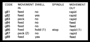
Multi-Hole Row Drilling
By the input to the control of one fixed cycle, a row of holes of a constant pitch can be produced if the total distance to be travelled (in) and the incremental distance (n2) are inserted. The format of this cycle is: (GB1) Xn, Xn2 IZn3 or (G81) Yn1 Yn2 (Zn3F).
SPECIAL MILL CYCLES G77, G78, G79
The control has three special mill cycles that reduce programming time and tape length for certain operations. These are:
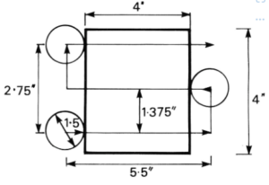
G77 Face Milling Cycle
This cycle enables the milling of a face of a component with any diameter cutter with only one line of data input to the control. The information required in this line is the distance to be milled in the X and Y axes and the incremental step over value in the Y axis to suit the diameter of the cutter to be used. Example: G77 X5.5 Y2.75 Y1.375 f 100.
G78 Pocket Milling Cycle
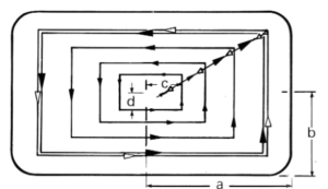
This cycle enables the milling of a face of a component with any diameter cutter with only one line of data input to the control. The information required in this line of data is the dimension of the pocket (a and b) less the cutter radius and the X and Y incremental step over values (c and d) i.e. G78 Xa Xc Yb Yd federate.
The cycle starts from the centre of the pocket, the first move will be an X and Y axis step-over. The cutter will then move – X, -Y, +x, +Y at a value equal to twice the accumulated step-over distance. The cutter will then make another XY step-over move. This will continue until the cutter is within 0.5mm (0.020”) of the pocket well. The last step-over move will be 0.5mm (0.020”) in both X and Y followed by a rectangle cut at a federate 50% higher than the input federate. The cutter will then feed to the centre of the pocket to end the cycle.
G79 Internal Hole Mill Cycle
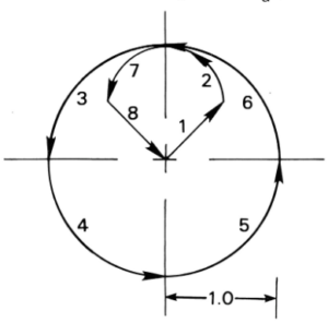
Internal holes can be milled with only one line of data input to the control, this being the dimension of the radius ® of the hole to be milled minus the cutter radius i.e. G79Jr Feedrate.
Example:
G79J1.0F100 – inch mode
G71 G79J25.4F254 – metric mode
Will mill a hole 1.0” (25.4mm) radius (plus cutter radius) at a feed rate of 10”/min (254mm/min).
Without the use of the G79 cycle this would have been programmed:
N01G91G1X.5Y.5F100
N02G99G3X-.5Y.51.5
N03G99X-1.0Y-1.0J1.0
N04G99I1.0
N05G99J1.0
N06G9911.0
N07X-.5Y-.5J.5
N08G1X.5Y-.5
Repetitive Programming
The Bridgeport CNC provides two different ways of accomplishing repetitive programming without the tedious monotony of writing down the same commands over and over again. These programming techniques are referred to as Looping and Macro sub-routines.
Looping provides the programmer with the ability to jump back to an earlier line of programme text and execute the intervening lines of programme text a specified number of times. The looping feature of the Bridgeport CNC is a technique that instructs the computer to read and interpret a set of statements in the part programme as many times as indicated by the programmer, significantly reducing the programming effort.
The looping part-programme statement is of the following form: = Na/b where a is the loop end block sequence number, b is the number of times the loop is to be repeated.
Following a loop statement all the part programme blocks in the range of the loop are executed. This process continues until the repeat register is zero. Loops may be nested within loops up to 4 levels.
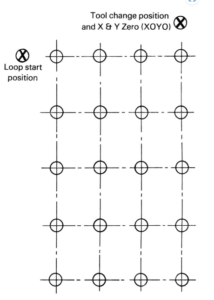
LOOP EXAMPLE:
N105G0G90X0Y0T1M6
N110X0.5Y-1.0Z-0.95
=N135/2
N115G81G91X-.5Z.71F44
=N120/4
N120Y-1.0
N125X-.5
=N130/4
N130Y1.0
N135
N140G0G90X0Y0T2M6
Macros provide the programmer with the ability to define a sub-programme which may be stored in the control and executed as many times as required within the duration of the main programme. Variable parameters can be inserted in the macro to enable a change in the value of the addressed parameters on execution of the sub-programme.
MACRO EXAMPLE:
# 1
N50G0G90X-4.0Y4.0T*M6
N55X-1.5Y1.5Z-.95
N60G81X-1.5Z*F*
N65X1.5
N70Y-1.5
N75X-1.5
$
The Macro all statements are:
= # 1T*Z* .245F*56 (Spot Drill)
= # 1T*2Z* 1.212F*44 (Drill)
Macros may be called within macros up to 4 levels and may also include loops. Up to 36 macro sub-programmes can be designated at any one time within a programme.
OPERATOR’S CONTROLS
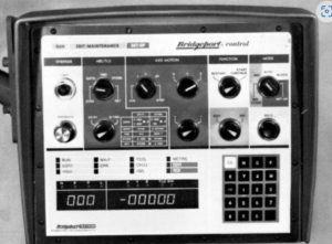
Main Panel
The operator’s control panel is mounted at the right of the ram on a short sturdy moveable arm to permit convenient positioning.
The panel is an integral nit internally wired to the interface located in the machine control panel. It provides the operator with full control in automatic, manual and set up modes and is color coded and clearly captioned for operation with a minimum of training.
To facilitate manual operation a 20 button manual data input keyboard is provided. This enables the operator to input tool length offsets and also manually programme simple operations of the machine in linear interpolation. Input information may also be stored, thus providing an alternative method to tape preparation for multiple programme execution.
The facility is available to call-up the value of the programmed X, Y or Z co-ordinates, federate and programme block sequence number of the display panel.
The machine operation safety features incorporated in the panel are:
- The axis limit override isolates power from the axis stepping motors if any traverse limit is exceeded.
- The facility to override the programmed federate within an infinitely variable range from 0 – 120%
- The hold button which when activated ensures the smooth stopping of the axis movement without loss of position. No information is lost from active register therefore allowing the programme to continue uninterrupted from the momentary stop position.
Spindle Control Panel
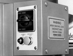
This houses the spindle stop/start control and emergency stop button
Stop Button The spindle stop light is illuminated when a tool change is indicated by the control i.e. the spindle stops and the stop light indicates a safe condition. As a safety feature the spindle and cut feed rates are interlocked.
Special Operations Panel
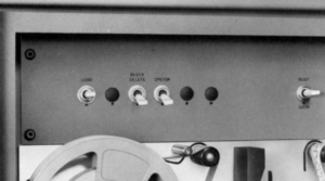
This panel situated above the tape reader provides the facility:
- To clear the memory of the micro-computer thus allowing the loading and storage of new data
- For the deletion of specific lines of data in the part programme
- To incorporate an optional stop in the part programme
Tape Reader
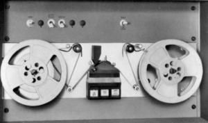
The tape reader provides a method of inputting data into the micro-computer memory via a pre-punched paper tape. The maximum storage capacity is equivalent to 24m. (80ft.) of tape. If the length of the input tape is known to be greater than the storage capacity a real time control feature enables the control to segment the main programme into equivalent 24m (80ft) sections.
CONTROL CABINETS
There are two such units mounted to the machine column. The power Transformers Cabinet is mounted at the back and the Logic Control Cabinet on the right hand side.
REGULATED SYSTEM POWER SUPPLIES. The three phase main breaker applies power to the control. BOSS comes up fully operational with power application and in the “initialized” state with no power in the axis drive system. Filters on the input AC lines trap electrical noise transients generated by external equipment. The logic will not misfunction if the AC power source is temporarily interrupted for 1/60 second of less. Longer interruptions will cause the system to automatically “initialize” when power resumes. When power is turned off at the Main breaker – the entire part programme text is destroyed and must be reloaded.
AXIS POWER SUPPLIES. Besides the logic compartment and tape reader, the control console houses three separate power supplies, one for each axis. The output of each power supply is suitably rectified for accelerations and static positioning purposes. The low level switching logic is amplified and couples with current feedback from the motor to become the high power DC source for the power drivers to give the step motor the high torque throughout its speed range. Illumination of the LIMIT OVERRIDE indictor on the Operator’s Control Panel, signifies no power in the axis drive system.
LOGIC CONTROL CABINET. The column mounted cabinet is designed to combine all necessary functions, providing maximum access. The construction is such that equipment is protected from the dust normally found in a non-air-conditioned factory environment. Internally mounted fans provide a cooling air system for the equipment, ambient air being drawn through filters and exhausted through a properly baffled series of outlet ducts. They system is designed and constructed to operate continually in a normal environment.
SAFETY INTERLOCKS. An interlock device prevents the tool from feed unless power to the spindle is on.

STANDARD FEATURES – CONTROL
Maintenance Diagnostics
An on-line debugging micro programme enables the examination of all system registers via the operator’s main control panel.
OPTIONAL FEATURES – CONTROL
External Data Input Terminal/Text Editor
A 20ma serial line interface is supplied on the control capable of handling the transmission of data between the micro-computer and an external data input terminal.
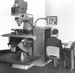
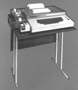
A teleprinter complete with interface lead is available as optional equipment and suitable stand can also be supplied if required.
The teleprinter can be used independently for the initial programme tap preparation. With the teleprinter connected to the control it provides an alternative method for inputting data from a paper tape to the micro-computer. As a text editor, the teleprinter allows the operator to change or modify the part programme utilizing the Bridgeport CNC 16 edit command characters. A punched paper tape and programme copy of the modified programme can be produced through the teleprinter.
Postprocessors
Postprocessors for APT/DAPT computer assisted parts programming.
STANDARD FEATURES
Manuals
Supplied with the machine are:
- Operators manual
- Programming Manual
- A manual is also supplied with the Postprocessor option.
OPTIONAL FEATURES
Chip/Coolant Shield
The shield is made of a clear material (Lexan or equivalent) having high impact resistance to provide operator safety and a clear unobstructed view of the component and cutter. A door at the front allows easy access for tool changing or loading of components. This shield is supplied as an option in accordance with the Health and Safety At Work Act 1974.
Coolant
A flood coolant pump and fittings can be supplied. The centrifugal pump is mounted inside the column and suitable piping is provided to supply coolant to the cutter and to return it from the table to the coolant tank in the base of the machine.
A spray mist coolant system is also available and features a reservoir mounted on the machine column. A jet assembly, comprising a flexible extension, jet and jet tip supplies the coolant spray to the cutting edge. An external source of compressed air supply is required.
Splash Tray
The spacious splash tray is extremely advantageous when coolant is used liberally and is easily removed for cleaning purposes.
Tooling Package
A choice of comprehensive Bristol Erickson N.30 International Quick Change tooling packages can be supplied. Contained in a specially designed box to provide safe storage and ease accessibility.
Images and Catalog via: http://www.lathes.co.uk/bridgeport

